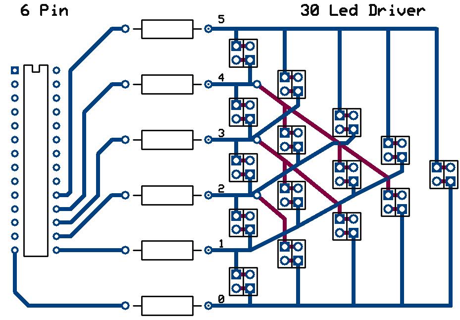
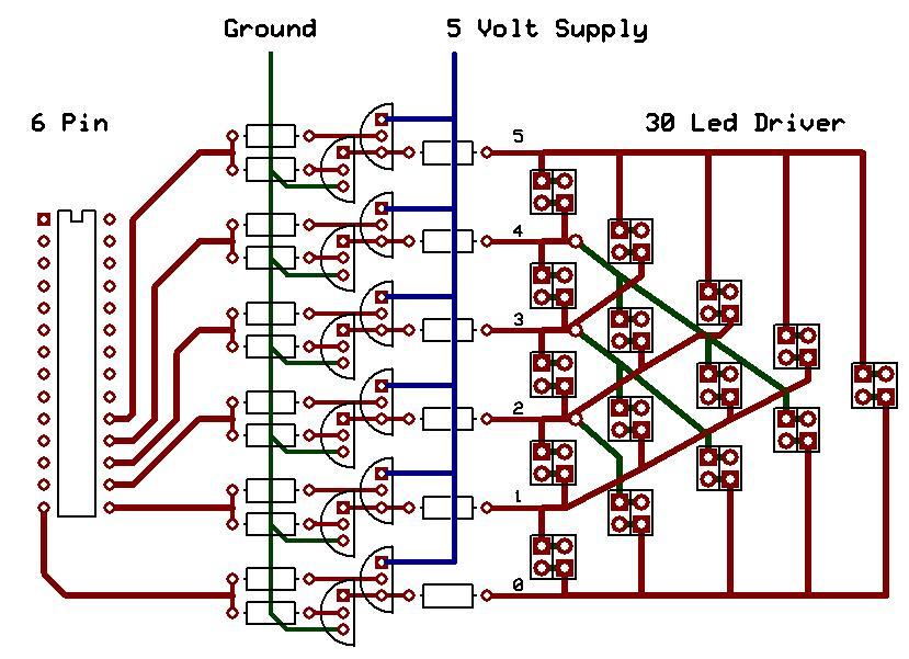
Control 30 LEDS With 6 Pins On The ATmega168 Microcontroller
If under 20mA
If over 20mA use 6 PNP's and NPN's
#include <avr/io.h>
#include <avr/interrupt.h>

#define B0 0x01	// 0b00000001
#define B1 0x02	// 0b00000010
#define B2 0x04	// 0b00000100
#define B3 0x08	// 0b00001000
#define B4 0x10	// 0b00010000
#define B5 0x20	// 0b00100000

uint8_t volatile blinkLEDs = 1;

int main(void)
{
	//*****************************************      Setup 8-bit Timer 0      *****************************************//
	TCCR0A = 0b00000010;		// |COM0A1|COM0A0|COM0B1|COM0B0|0|0|WGM01|WGM00|
					// COMA and COMB are set to normal,  OC0A and OC0B are disconnected respectively
					// WGM is set to CTC - Clear Timer on Compare (of OCR0A) Mode#2 = 010

	TCCR0B = 0b00000000;		// |FOC0A|FOC0B|0|0|WGM02|CS02|CS01|CS00|
					// FOC set to default - WGM02 set to 0 - Clock set to off

	TIMSK0 = 0b00000010;		// |0|0|0|0|0|OCIE0B|OCIE0A|TOIE0|
					// Timer Output Compare Match Interrupt A is enabled

	TIFR0  = 0b00000000;		// |0|0|0|0|0|OCFOB|OCF0A|TOV0|
					// Flags are set to 0 - Default settings

	OCR0A = 255;			//

	sei();				// Enables the global registers.

	TCCR0B = 0b00000101;		// |FOC0A|FOC0B|0|0|WGM02|CS02|CS01|CS00|
					// Turn On Clock and set speed selection to Clock/1024
    while(1)
    {
    }
}

ISR(TIMER0_COMPA_vect)
{
	switch (blinkLEDs)
	{
		case 1:		DDRB = B0|B1; PORTB = B0;blinkLEDs++;break;
		case 2:		DDRB = B0|B1; PORTB = B1;blinkLEDs++;break;
		case 3:		DDRB = B0|B2; PORTB = B0;blinkLEDs++;break;
		case 4:		DDRB = B0|B2; PORTB = B2;blinkLEDs++;break;
		case 5:		DDRB = B0|B3; PORTB = B0;blinkLEDs++;break;
		case 6:		DDRB = B0|B3; PORTB = B3;blinkLEDs++;break;
		case 7:		DDRB = B0|B4; PORTB = B0;blinkLEDs++;break;
		case 8:		DDRB = B0|B4; PORTB = B4;blinkLEDs++;break;
		case 9:		DDRB = B0|B5; PORTB = B0;blinkLEDs++;break;
		case 10:	DDRB = B0|B5; PORTB = B5;blinkLEDs++;break;

		case 11:	DDRB = B1|B2; PORTB = B1;blinkLEDs++;break;
		case 12:	DDRB = B1|B2; PORTB = B2;blinkLEDs++;break;
		case 13:	DDRB = B1|B3; PORTB = B1;blinkLEDs++;break;
		case 14:	DDRB = B1|B3; PORTB = B3;blinkLEDs++;break;
		case 15:	DDRB = B1|B4; PORTB = B1;blinkLEDs++;break;
		case 16:	DDRB = B1|B4; PORTB = B4;blinkLEDs++;break;
		case 17:	DDRB = B1|B5; PORTB = B1;blinkLEDs++;break;
		case 18:	DDRB = B1|B5; PORTB = B5;blinkLEDs++;break;

		case 19:	DDRB = B2|B3; PORTB = B2;blinkLEDs++;break;
		case 20:	DDRB = B2|B3; PORTB = B3;blinkLEDs++;break;
		case 21:	DDRB = B2|B4; PORTB = B2;blinkLEDs++;break;
		case 22:	DDRB = B2|B4; PORTB = B4;blinkLEDs++;break;
		case 23:	DDRB = B2|B5; PORTB = B2;blinkLEDs++;break;
		case 24:	DDRB = B2|B5; PORTB = B5;blinkLEDs++;break;

		case 25:	DDRB = B3|B4; PORTB = B3;blinkLEDs++;break;
		case 26:	DDRB = B3|B4; PORTB = B4;blinkLEDs++;break;
		case 27:	DDRB = B3|B5; PORTB = B3;blinkLEDs++;break;
		case 28:	DDRB = B3|B5; PORTB = B5;blinkLEDs++;break;

		case 29:	DDRB = B4|B5; PORTB = B4;blinkLEDs++;break;
		case 30:	DDRB = B4|B5; PORTB = B5;blinkLEDs=1;break;
	}
}
#include <avr/io.h>
#include <avr/interrupt.h>

#define B0 0x01	// 0b00000001
#define B1 0x02	// 0b00000010
#define B2 0x04	// 0b00000100
#define B3 0x08	// 0b00001000
#define B4 0x10	// 0b00010000
#define B5 0x20	// 0b00100000

uint8_t volatile  counterMax	= 5;		// Total number of Pins from 0 (ie 0 to 5 = 6 pins)
uint8_t volatile  counter		= 1;
uint8_t volatile  startPin		= B0;
uint8_t volatile  currentPin	= 0;
uint8_t volatile  turnOn1st		= 1;

int main(void)
{
	//*****************************************      Setup 8-bit Timer 0      *****************************************//
	TCCR0A = 0b00000010;		// |COM0A1|COM0A0|COM0B1|COM0B0|0|0|WGM01|WGM00|
					// COMA and COMB are set to normal,  OC0A and OC0B are disconnected respectively
					// WGM is set to CTC - Clear Timer on Compare (of OCR0A) Mode#2 = 010

	TCCR0B = 0b00000000;		// |FOC0A|FOC0B|0|0|WGM02|CS02|CS01|CS00|
					// FOC set to default - WGM02 set to 0 - Clock set to off

	TIMSK0 = 0b00000010;		// |0|0|0|0|0|OCIE0B|OCIE0A|TOIE0|
					// Timer Output Compare Match Interrupt A is enabled

	TIFR0  = 0b00000000;		// |0|0|0|0|0|OCFOB|OCF0A|TOV0|
					// Flags are set to 0 - Default settings

	OCR0A = 255;			//

	sei();				// Enables the global registers.

	TCCR0B = 0b00000101;		// |FOC0A|FOC0B|0|0|WGM02|CS02|CS01|CS00|
					// Turn On Clock and set speed selection to Clock/1024
    while(1)
    {
    }
}

ISR(TIMER0_COMPA_vect)
{
		DDRB = (startPin |(startPin<<counter));
		if(turnOn1st)
		{
			PORTB = startPin;
			turnOn1st = 0;
		}
		else
		{
			PORTB = (startPin<<counter);
			turnOn1st = 1;

			if(counter == counterMax)
			{
				startPin <<= 1;				// startPin = startPin << 1
				currentPin++;
				counterMax--;
				if (counterMax == 0)
				{
						startPin = B0;
						currentPin	= 0;
						counterMax  = 5;
				}
				counter = 0;
			}
			counter++;
		}
}
#include <avr/io.h>
#include <avr/interrupt.h>
#include <inttypes.h>
#include <avr/pgmspace.h>

#define NUM_LEDS	30
#define B0 0x01	// 0b00000001
#define B1 0x02	// 0b00000010
#define B2 0x04	// 0b00000100
#define B3 0x08	// 0b00001000
#define B4 0x10	// 0b00010000
#define B5 0x20	// 0b00100000

typedef struct
{
	uint8_t ddr;
	uint8_t port;
} PortAndDDRState;

PortAndDDRState const PROGMEM leds[NUM_LEDS] =	{
								{ B0 | B1,	B0 },	// LED 1
								{ B0 | B1,	B1 },	// LED 2
								{ B0 | B2,	B0 },	// LED 3
								{ B0 | B2,	B2 },	// LED 4
								{ B0 | B3,	B0 },	// LED 5
								{ B0 | B3,	B3 },	// LED 6
								{ B0 | B4,	B0 },	// LED 7
								{ B0 | B4,	B4 },	// LED 8
								{ B0 | B5,	B0 },	// LED 9
								{ B0 | B5,	B5 },	// LED 10

								{ B1 | B2,	B1 },	// LED 11
								{ B1 | B2,	B2 },	// LED 12
								{ B1 | B3,	B1 },	// LED 13
								{ B1 | B3,	B3 },	// LED 14
								{ B1 | B4,	B1 },	// LED 15
								{ B1 | B4,	B4 },	// LED 16
								{ B1 | B5,	B1 },	// LED 17
								{ B1 | B5,	B5 },	// LED 18

								{ B2 | B3,	B2 },	// LED 19
								{ B2 | B3,	B3 },	// LED 20
								{ B2 | B4,	B2 },	// LED 21
								{ B2 | B4,	B4 },	// LED 22
								{ B2 | B5,	B2 },	// LED 23
								{ B2 | B5,	B5 },	// LED 24

								{ B3 | B4,	B3 },	// LED 25
								{ B3 | B4,	B4 },	// LED 26
								{ B3 | B5,	B3 },	// LED 27
								{ B3 | B5,	B5 },	// LED 28

								{ B4 | B5,	B4 },	// LED 29
								{ B4 | B5,	B5 }	// LED 30
							};
uint8_t volatile nextLED = 0;

int main(void)
{
	//*****************************************      Setup 8-bit Timer 0      *****************************************//
	TCCR0A = 0b00000010;		// |COM0A1|COM0A0|COM0B1|COM0B0|0|0|WGM01|WGM00|
					// COMA and COMB are set to normal,  OC0A and OC0B are disconnected respectively
					// WGM is set to CTC - Clear Timer on Compare (of OCR0A) Mode#2 = 010

	TCCR0B = 0b00000000;		// |FOC0A|FOC0B|0|0|WGM02|CS02|CS01|CS00|
					// FOC set to default - WGM02 set to 0 - Clock set to off

	TIMSK0 = 0b00000010;		// |0|0|0|0|0|OCIE0B|OCIE0A|TOIE0|
					// Timer Output Compare Match Interrupt A is enabled

	TIFR0  = 0b00000000;		// |0|0|0|0|0|OCFOB|OCF0A|TOV0|
					// Flags are set to 0 - Default settings

	OCR0A = 255;			//

	sei();				// Enables the global registers.

	TCCR0B = 0b00000101;		// |FOC0A|FOC0B|0|0|WGM02|CS02|CS01|CS00|
					// Turn On Clock and set speed selection to Clock/1024
    while(1)
    {
    }
}

ISR(TIMER0_COMPA_vect)
{
	uint8_t ledNum	= nextLED;
	uint8_t ddr	= pgm_read_byte (&leds[ledNum].ddr);
	uint8_t port	= pgm_read_byte (&leds[ledNum].port);

	DDRB = ddr;
	PORTB = port;

	if (++ledNum == NUM_LEDS)	{ledNum = 0;}

	nextLED = ledNum;
}